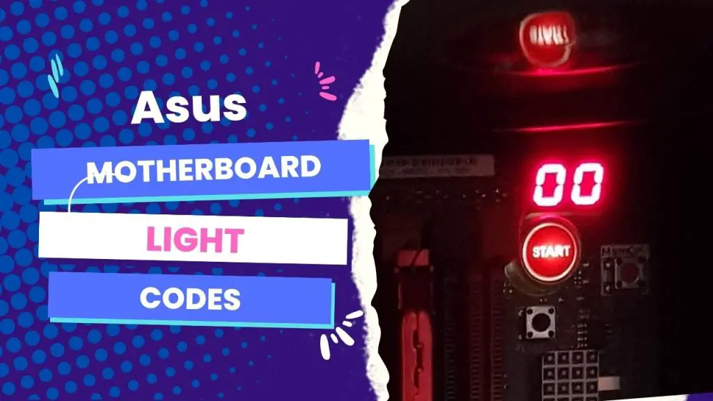
The most common Asus motherboard light code is 00, which means there is no error and that the system is starting up normally. Other common codes include:
- 50-54: Memory initialization errors
- 55: Memory not installed
- 56-57: Invalid CPU type or speed/CPU mismatch
- 62: Installation of the PCH Runtime Services
- 76: PCH DXE Initialization (PCH Module Specific)
- 99: Super IO Initialization
- A0: IDE Initialization Is Started
- A2: IDE Detect
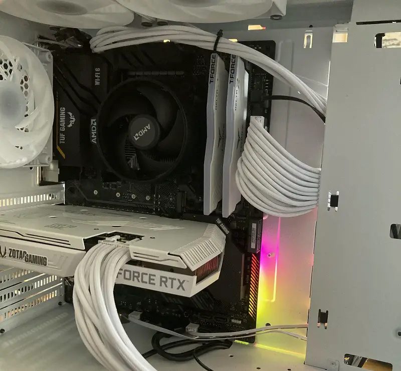
Other common Asus Motherboard Light Codes include the BOOT_DEVICE_LED, VGA_LED, DRAM_LED, and CPU_LED. These four post-state LEDs will indicate if there is a fault stopping the BIOS from Posting. Most newer ASUS motherboards (the B250F, for example) have, other than the RGB LEDs, four solid- 4 post-state LED indicators designed close to the 24-pin connector and a standby power LED next to the SATA ports.
If you see one of these codes, you can try troubleshooting the problem by following the instructions in this article.
In this article, you will learn about ASUS motherboard light codes, their meaning, and the required troubleshooting steps for these LED codes.
Most Common Asus Light Q-Codes and Meaning
| Code | Description |
|---|---|
| 00 | Not used |
| 01 | Power on. Reset type detection (soft/hard). |
| 02 | AP initialization before microcode loading |
| 03 | System Agent initialization before microcode loading |
| 04 | PCH initialization before microcode loading |
| 06 | Microcode loading |
| 07 | AP initialization after microcode loading |
| 08 | System Agent initialization after microcode loading |
| 09 | PCH initialization after microcode loading |
| 0A | Initialization after microcode loading |
| 0B | Cache initialization |
| 0C – 0D | Reserved for future AMI SEC error codes |
| 0E | Microcode not found |
| 0F | Microcode not loaded |
| 10 | PEI Core is started |
| 11 – 14 | Pre-memory CPU initialization is started |
| 15 – 18 | Pre-memory System Agent initialization is started |
| 19 – 1C | Pre-memory PCH initialization is started |
| 2B – 2F | Memory initialization |
| 30 | Reserved for ASL (see ASL Status Codes section below) |
| 31 | Memory Installed |
| 32 – 36 | CPU post-memory initialization |
| 37 – 3A | Post-Memory System Agent initialization is started |
| 3B – 3E | Post-Memory PCH initialization is started |
| 4F | DXE IPL is started |
| 50 – 53 | Unspecified memory initialization error |
| 54 | Invalid memory type or incompatible memory speed |
| 55 | Memory not installed |
| 56 | Invalid CPU type or Speed |
| 57 | CPU mismatch |
| 58 | CPU self test failed or possible CPU cache error |
| 59 | CPU micro-code is not found or micro-code update is failed |
| 5A | Internal CPU error |
| 5B | Reset PPI is not available |
| 5C – 5F | Reserved for future AMI error codes |
| E0 | S3 Resume is stared (S3 Resume PPI is called by the DXE IPL) |
| E1 | S3 Boot Script execution |
| E2 | Video repost |
| E3 | OS S3 wake vector call |
| E4 – E7 | Reserved for future AMI progress codes |
| E8 | S3 Resume Failed |
| E9 | S3 Resume PPI not Found |
| EA | S3 Resume Boot Script Error |
| EB – EF | Reserved for future AMI error codes |
| F0 | Recovery condition triggered by firmware (Auto recovery) |
| F1 | Recovery condition triggered by user (Forced recovery) |
| F2 | Recovery process started |
| F3 | Recovery firmware image is found |
| F4 | Recovery firmware image is loaded |
| F5 – F7 | Reserved for future AMI progress codes |
| F8 | Recovery PPI is not available |
| F9 | Recovery capsule is not found |
| FA | Invalid recovery capsule |
| FB – FF | Reserved for future AMI error codes |
| 60 | DXE Core is started |
| 61 | NVRAM initialization |
| 62 | Installation of the PCH Runtime Services |
| 63-67 | CPU DXE initialization is started |
| 68 | PCI host bridge initialization |
| 69 | System Agent DXE initialization is started |
| 6A | System Agent DXE SMM initialization is started |
| 6B | System Agent DXE initialization (System Agent module specific) |
| 6C | PCH DXE initialization is started |
| 6D | PCH DXE SMM initialization is started |
| 6E | PCH devices initialization |
| 6F | PCH DXE Initialization (PCH module specific) |
| 70 | ACPI module initialization |
| 71 | CSM initialization |
| 72 | Reserved for future AMI DXE codes |
| 73 | Boot Device Selection (BDS) phase is started |
| 74 | Driver connecting is started |
| 75 | PCI Bus initialization is started |
| 76 | PCI Bus Hot Plug Controller Initialization |
| 77 | PCI Bus Enumeration |
| 78 | PCI Bus Request Resources |
| 79 | PCI Bus Assign Resources |
| 7A | Console Output devices connect |
| 7B | Console input devices connect |
| 7C | Super IO Initialization |
| 7D | USB initialization is started |
| 7E | USB Reset |
| 7F | USB Detect |
| 90 | USB Enable |
| 91 | Reserved for future AMI codes |
| 92 | IDE initialization is started |
| 93 | IDE Reset |
| 94 | IDE Detect |
| 95 | IDE Enable |
| 96 | SCSI initialization is started |
| 97 | SCSI Reset |
| 98 | SCSI Detect |
| 99 | SCSI Enable |
| 9A | Setup Verifying Password |
| 9B | Start of Setup |
| 9C | Reserved for ASL (see ASL Status Codes section below) |
| 9D | Setup Input Wait |
| 9F | Reserved for future AMI codes |
| A0 | IDE initialization is started |
| A1 | IDE Reset |
| A2 | IDE Detect |
| A3 | IDE Enable |
| A4 | SCSI initialization is started |
| A5 | SCSI Reset |
| A6 | SCSI Detect |
| A7 | SCSI Enable |
| A8 | Setup Verifying Password |
| A9 | Start of Setup |
| AA | Reserved for ASL (see ASL Status Codes section below) |
| AB | Setup Input Wait |
| Code | Description |
|---|---|
| AC | Reserved for ASL (see ASL Status Codes section below) |
| AD | Ready To Boot event |
| AE | Legacy Boot event |
| AF | Exit Boot Services event |
| B0 | Runtime Set Virtual Address MAP Begin |
| B1 | Runtime Set Virtual Address MAP End |
| B2 | Legacy Option ROM Initialization |
| B3 | System Reset |
| B4 | USB hot plug |
| B5 | PCI bus hot plug |
| B6 | Clean-up of NVRAM |
| B7 | Configuration Reset (reset of NVRAM settings) |
| B8-BF | Reserved for future AMI codes |
| D0 | CPU initialization error |
| D1 | System Agent initialization error |
| D2 | PCH initialization error |
| D3 | Some of the Architectural Protocols are not available |
| D4 | PCI resource allocation error. Out of Resources |
| D5 | No Space for Legacy Option ROM |
| D6 | No Console Output Devices are found |
| D7 | No Console Input Devices are found |
| D8 | Invalid password |
| D9 | Error loading Boot Option (LoadImage returned error) |
| DA | Boot Option is failed (StartImage returned error) |
| DB | Flash update is failed |
| DC | Reset protocol is not available |
| 0X01 | System is entering S1 sleep state |
| 0X02 | System is entering S2 sleep state |
| 0X03 | System is entering S3 sleep state |
| 0X04 | System is entering S4 sleep state |
| 0X05 | System is entering S5 sleep state |
| 0X10 | System is waking up from the S1 sleep state |
| 0X20 | System is waking up from the S2 sleep state |
| 0X30 | System is waking up from the S3 sleep state |
| 0X40 | System is waking up from the S4 sleep state |
| 0XAC | System has transitioned into ACPI mode. Interrupt controller is in PIC mode |
| 0XAA | System has transitioned into ACPI mode. Interrupt controller is in APIC mode |
How Do You Confirm Your Asus Motherboard Supports the Q-Led Indicator?
Before we dive into troubleshooting what these codes are, you should know that not all Asus motherboards are designed with light code. Especially for older Asus models, they may only have beep codes. So you should first verify that your unit supports LED debug codes.
There are three ways to check that your Asus motherboard supports Q-LED indicators:
- By inspecting your motherboard to find the Q-LED indicator interface
- By visiting the ASUS official website, and
- By checking the Asus user manual.
Check your motherboard
- Look at the area where you have the 24-pin power supply interface or memory slot on your motherboard to confirm if you can find the Q-LED indicator.
- If you see it there, then your Asus build supports the feature. However, some older models like Z97-mark_ S have their Q-LED light located on their respective slot (The VGA_LED light near the PCIE slot, for example)
Via the ASUS Official website
- You can check if your model supports ASUS Q-LED by looking at the official website.
- First, navigate to the search bar on the website and type in your model name.
- On the result page, you click “Specifications,” find “Special Features,” then “ASUS Q-Design” Check if the ASUS Q-LED is supported for the model.
Via User Manual
- You first want to download the user manual for your motherboard through the ASUS Support Center.
- On the page, input your model name, and select “Manual & Document.”
- Then, you click “Manual,” find your model in Manual (English), and download it.
- On the manual, search for “Special features > ASUS Q-Design > Q-LED
Now that you’ve verified that your Asus motherboard supports Q-LED codes, you can now learn about the various Asus motherboard light codes and how to debug them.
Asus Motherboard Light Codes – Meaning & Fixes
DRAM light (quick flashing on the Power LED)
If your Q-LED indicators have quick flashing on the power LED or show the DRAM light, try the following steps to solve the problem:
Step 1: Remove the power cord
Step 2: Confirm your memory card is fully installed or try to re-install it. While you try to re-install it, clean the memory card fingers and the slot on the motherboard if necessary.
Step 3: You can also follow the recommended memory configurations in your user manual to change your memory to other slots.
If the light continues to flash after you have completed the preceding steps, you must replace your DRAM with one from the support list (QVL list) of your motherboard, which is available from the Asus support site.
VGA light (Slow flashing on Power LED)
If the VGA light is on or you find the power LED slowly flashing, consider trying the following debug fixes:
Step 1: Check and reconnect the display cable between your monitor and the VGA output. Before doing anything else, ensure the power cord is removed.
Step 2: Unplug the PCI-E power cable and the external graphics card
Step 3: Clean the graphics card fingers and slots before re-installing them back
Step 4: Reconnect the display cable to your monitor and the VGA output and see if the problem is solved.
Meanwhile, if you use a newer Asus motherboard model, check on the AMD website to see if your CPU supports the integrated graphics display.
Boot light (Super slow flashing on Power LED)
If the BOOT light is on or the power LED is flashing super slowly (8-second blinking sequence, for example), it means something went wrong during the system booting process. To solve the issue, follow these steps:
Step 1: Go to the Advance mode in BIOS and check if your booting device is there and in the first booting priority
Step 2: Turn off the system and remove the power and confirm the boot device is well installed
Step 3: Also consider removing your HDD, SSD, or M.2 SSD, clean and re-install them back to check if there are any damaged parts
If your booting device is not working anymore, change it and try again.
CPU light
When the CPU light remains in the Q-LED indicators, follow these debugging steps:
Step 1: First, remove the power cord, loosen the four cooler pins, and remove the cooler without pulling the CPU out of the heatsink
Step 2: Flip the retention arm to loosen the metal clamp that holds the CPU in place
Step 3: Lift the socket lid
Step 4: Use two fingers to lift the CPU out of its socket. Lift it directly upward and take the CPU out.
Step 5: Check and clean the CPU contacts if there is any dust on them. You can also check whether the CPU pins are bent or not.
If they are damaged, you will have to contact Asus customer service for the repair process.
Step 6: Matching the nubbins in the corner of the CPU socket can help you place the CPU back easily
Step 7: Install your cooler firmly and properly in the right position.
If, after trying the above steps, the CPU light remains on, you can consider upgrading your BIOS to the latest version via the Asus website. Also, confirm that your CPU is on the CPU support list for your motherboard.
How do I disable the Q-Code LED light on my Asus motherboard?
You can also disable the LED code light on your Asus motherboard. You’d have the motivation to do this when the light keeps coming on, even when there is no issue with your motherboard.
First, make sure you have the latest BIOS version installed on your computer. Then follow these steps:
Step 1: Restart your system and load it into your BIOS
Step 2: Click the AURA ON/OFF (F4) button in the upper-right corner of the screen. This will pop up four different lighting options, each with their own
Step 3: You can use “Stealth Mode” to turn everything off, but if you like to use the hardware RGB lighting (using Aura), then there are no issues.
The stealth mode, however, will disable every LED on the motherboard except the red Q-Code LED, which will still be functional.
If you want to disable the red light code, follow these steps:
Step 1: Switch to the Advanced tab on the BIOS
Step 2: Click ROG Effects.
Step 3: There are two motherboard LED options on this page, but only change the Onboard LED to Disabled for the remaining LEDs to be disabled. Also, change the Q-Code LED function to disabled after posting.
Step 4: Save the settings by clicking Exit in the top right corner
Step 5: Save Changes and Reset
Once you accept the change, your computer will reboot normally with all the changes active.
P.S.: Even after disabling ASUS light codes on your motherboard, you may still notice some tiny LEDs on the board, but you will barely notice them – they are less distracting (that’s even when they are not covered by cables or overshadowed by other hardware.
In Summary
ASUS motherboards are designed with four solid-state LED indicators, usually near the 24-pin connector (CPU_LED) and a standby power LED next to the SATA ports.
These light codes are BOOT_DEVICE_LED, VGA_LED, DRAM_LED, and CPU_LED; they all have different meanings and debugging steps. Their function is to indicate when there is a fault stopping the BIOS from posting.
However, most older or cheaper motherboards usually don’t have any sort of debug code displays, so they use beeps instead.


![Asus Motherboard Keeps Booting Into BIOS [Solutions] 3 Asus Motherboard Keeps Booting Into BIOS](https://bestofmotherboard.com/wp-content/uploads/2022/02/Asus-Motherboard-Keeps-Booting-Into-BIOS.jpg)
![How to Configure Your Asus Motherboard RGB Lighting [Guide] 4 How to Configure Your Asus Motherboard RGB Lighting](https://bestofmotherboard.com/wp-content/uploads/2022/02/How-to-Configure-Your-Asus-Motherboard-RGB-Lighting.jpg)

